Features
Speed Link™ height-of-cut system adjusts both sides of the roller at the same time
The ultimate in quick and accurate height-of-cut adjustments: The Speed Link height-of-cut adjustment system ties both sides of the front roller together, allowing technicians to make height-of-cut adjustments simply by adjusting one end of the roller.
How does this innovative system accomplish a one-point height-of-cut adjustment? It all starts with the worm gear drives in the front-roller castings. The worm gear system rotates via hex bolts on the side of the rear-roller castings, adjusting the roller up and down. Simply turn the gears by turning the hex adjuster on the side of the casting. Each full turn represents an adjustment of 0.001 in. (0.0254 mm). A diagram on the side of the casting tells which direction to turn the hex bolts to raise or lower the cutting height.
But that's not all. The true secret to the system is the connecting rod that ties the worm gear systems for the roller tower together. With the connecting rod in place, turning the height-of-cut adjuster on one side automatically turns the other side by the exact same amount. This allows for adjusting the height of cut from one end of the roller, making adjustments not only quick, but with stunning precision.
The Speed Link connecting rod is also spring loaded, so it can be easily removed should both towers need to be adjusted independently. Once the roller is paralleled to the front roller when the cutting unit is initially set up, the Speed Link system takes over and moves each side of the roller by the same amount for a quick one-point height-of-cut adjustment.
The preferred way to adjust the cutting unit is with a variable-speed electric or air drill with a 16-mm socket attached. A drill makes the adjustment even easier by rotating the tower quickly, making height-of-cut changes a breeze. And the connecting rod makes ensures the other side turns just as fast and just as accurately.
NOTE: Electric or pneumatic impact tools cannot be used to make the height-of-cut adjustment.
Consistent effective height of cut—A prism tells the story
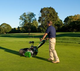 Effective height of cut
No matter the type of reel cutting unit or surface being mowed, there are two ways to measure height of cut. The first measure is called benchsetting height of cut. This height of cut is established by using a gauge bar and measuring the distance from the bottom of the rollers to the top edge of the bedknife. This serves as an initial guide for establishing the cutting height.
However, the cutting unit may not be mowing exactly at this height. Other factors come into play, such as softness or firmness of the mowing surface, thatch, turf density, roller shape and surface area, and weight, just to name a few. More than likely, after these factors are taken into consideration, the turf is being mowed at a height less than the benchsetting height of cut. The actual cutting height is called effective height of cut.
How is the effective height of cut measured? It can only be measured with a prism gauge, which uses a series of mirrors to visually show the horizontal profile of the turf. The prism essentially shows the turf rotated upward 90 degrees, so the actual height of cut can easily be seen.
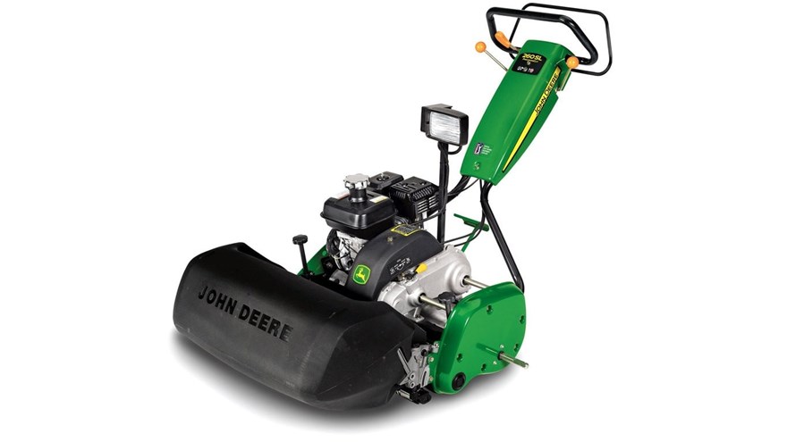
Understanding effective height of cut versus benchsetting height of cut is critical when evaluating a greens mower. Traditional fixed-head walk-behind greens mowers such as the 180SL, 220SL, and 260SL will almost always cut at a lower effective height of cut compared to recent floating-head walk-behind greens mowers.
In order to establish the same effective height of cut, the fixed-head walk-behind greens mower should be set at a higher benchsetting height of cut. Why? All of the weight of the fixed-head walk-behind greens mower is distributed to the rear drum and front roller. The weight on the actual cutting head of a floating-head mower comes from the cutting unit itself, not the traction unit. Essentially, the floating-head walk-behind greens mower is similar to a one-gang triplex in that regard.
So, isn't a floating-head walk-behind greens mower friendlier for the turf? The answer is no. Traditional fixed-head greens mowers stay engaged in the turf, helping to minimize thatch buildup and maintain a consistent height of cut. This may result in less thatch issues over time depending on other agronomic practices. Floating-head walk-behind greens mowers tend to ride over the top of the turf due to the light weight of the cutting unit actually in contact with the turf. This non-aggressive nature may result in significant thatch accumulation over time unless other agronomic practices are implemented.
Both types of mowers are affected by changing conditions. Both will require height-of-cut changes as conditions soften. The difference is that the 180SL, 220SL, and 260SL will always cut at a consistent height of cut due to their weight distribution and balance, whereas floating-head walk-behind greens mowers cannot make the same claim.
For maximum contour-following capability in severe undulations, the John Deere 180SL performs exceptionally. With a narrow 18-in. (45.7 cm) frame, fixed grass catcher, and narrow overlap, the productivity of the 180SL is roughly equal to that of 21-in. (53.34 cm) floating-head walk-behind greens mowers.
Roller attaching system for quick removal and installation of the front roller for changing conditions
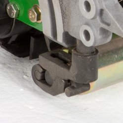 Front roller bracket
The ability to quickly adapt to the changing conditions is what golf courses have been doing for years. The SL model walk greens mowers from John Deere gives you the ability to meet the demanding needs of any green and helps you with the changing conditions.
The front roller bracket on the SL line gives you the ability to quickly change your front roller for the changing conditions that most greens see during the growing season. This gives you the ability to change from a grooved roller to a smooth roller with minimal effect on your bench setting and saves the time for the golf course technician.
How this feature works is each roller bracket has two sections that are bolted together to clamp the roller in place. The top section, connected to the Speed Link™ system, does not move when you remove the roller, thus keeping the height consistent. By removing the bottom bolt on each side, the front roller can be quickly removed from the machine, saving time and money while ensuring you have the correct roller for your condition.
Narrow front-roller-to-rear-drum distance for contour following and cleanup-pass cut quality
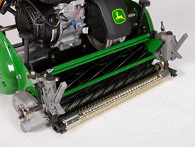 Narrow front-roller-to-rear-drum distance
The line of SL Walk Greens Mowers features a narrow front-roller-to-rear-drum distance for easy turning, maneuverability, and cleanup-pass cutting performance. With a Greens Tender™ Conditioner (GTC) installed, this distance is 13.5 in. (342 mm).
A narrow front-roller-to-rear-drum base increases performance in undulations, minimizing scalping opportunities and improving cut quality.
By keeping the roller base narrow, the John Deere SL models requires very little effort to lift the front roller to make a turn. As this distance increases, turning effort becomes much more difficult, reducing operator comfort during mowing.
Another benefit of the narrow front-to-rear base is maneuverability. By keeping the distance as short as possible, the machine becomes much easier to steer and requires little tracking effort on every pass. As this distance increases, opportunities for difficult steering and less-than-optimal tracking become much more prevalent.
These are important considerations when comparing to a floating-head walk-behind greens mower. Some of these competitive units feature front-roller-to-rear-drum distances that are up to 2.86 in. (72.6 mm) more than the John Deere SL models. This added distance increases lifting effort during turns and makes it more difficult to keep the machines on track.
Also important to note is the quality of cut in the cleanup pass. Cleanup passes are made in the same track every single time they are mowed. A longer machine with limited steering means the front roller drags across the turf in the cleanup pass, eventually thinning out the turf and hurting its quality. The John Deere SL models limit this impact with its narrow front-roller-to-rear-drum distance.
Grass-catcher system—Fixed to plane of reel for maximum performance in severe undulations
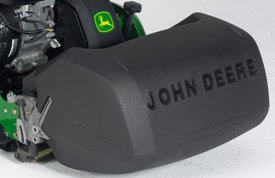 Grass catcher
The grass catcher is designed to retain clippings by slowing down the air volume and routing it out of the catcher while keeping the clippings in. Molded-in grooves and bullhorn-style mounting brackets make it easy to remove and replace the catcher. The catcher is made of lightweight polyethylene material that resists corrosion and cracking, reduces vibration, and is easy to use.
Overlap marks are molded into the top of the catcher for increased productivity and straightly mowed passes.
The grass-catcher system on the SL Walk Greens Mowers is fixed to the same plane as the reel. This means the grass catcher follows contours exactly as the reel does, maximizing the volume of grass thrown into the catcher. It also increases productivity by reducing the amount of overlap required.
Some competitive floating-head walk-behind greens mowers feature a grass catcher that is mounted to the traction unit frame, while allowing the reel to independently float in relationship to the catcher. In undulations, this means grass may get projected underneath the catcher on the ends of the cutting unit. As a result, more significant overlapping is required to ensure that all of the freshly cut grass gets thrown into the catcher, not underneath it. The increased overlapping required on the floating-head units makes the productivity of a 180SL roughly equal to that of a 21-in. (53.34 cm) floating-head greens mower.
The SL Walk Greens Mowers also feature a large-capacity grass catcher for a couple of reasons. First, a consistent effective height of cut means more grass is being cut and more grass is being thrown into the catcher. Second, increased capacity limits opportunities for grass clippings to fall out of the catcher when making turns.
Integrated gear reduction yields same quality of cut regardless of operator mowing speed
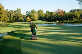 Engine gear reduction
The SL Walk-Behind Greens Mowers come standard with an engine gear reduction in the external differential drive. This mechanism automatically compensates the reel speed across the full-throttle range.
For a three-year-experienced operator who is comfortable mowing at a faster speed and a newer operator who operates at a slower speed, the frequency of clip between the operators is exactly the same. This is a function of the gear reduction. The faster the throttle speed, the faster the reel speed. And the slower the throttle, the slower the reel speed.
There is nothing the technician, operator, or superintendent needs to do to make this happen; it is an automatic system. Superintendents can feel confident that no matter if the operator is experienced or relatively new, the cut quality between the two will be the same.
Simple operator control design requires all controls to move forward for engagement
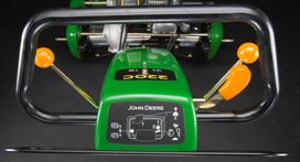 View of operator controls from operator station
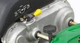 Reel engagement lever (disengaged position)
For ease of operation, all controls move forward for mowing:
-
The engine on/off switch is located on the front cover for easy access. The on position is forward, while the off position is backward.
-
The park brake lever is located to the left of the operator station. To disengage the parking brake, push the lever forward. To engage it, pull the lever back.
-
The throttle and clutch levers are located to the right-hand side of the operator station. To increase throttle, push the throttle lever forward. To engage the clutch, hold down the operator-presence bail and push the clutch lever forward, always starting out at low throttle and increasing the throttle to increase to desired speed. To release the clutch and stop the machine, simply release the operator-presence bail. The engine will remain running.
-
The reel engagement lever is located on the differential gearcase. To set up reel engagement, rotate the lever to the forward position. For transporting, rotate the lever to the rear position to keep the reel from rotating.
Standard operator-presence system — Quick release to disengage traction
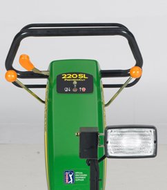 Operator's station
The 180SL, 220SL, and 260SL Walk Greens Mowers meet American National Standards Institute (ANSI) B71.4-2004 standards, which require an operator-presence system.
The standard operator-presence system features a spring-loaded bail mechanism to control machine traction. To engage traction, depress and hold the operator-presence bail against the handlebar and engage the traction clutch with the engine at low throttle. To disengage traction, release the operator-presence bail and the traction clutch lever automatically disengages.
The operator-presence bail is formed to allow the operator to easily fit the bail against the handlebar in virtually any hand position, including operators who mow by lifting up on the handlebar while mowing to reduce operator influence on the cutting height. The bail easily accommodates loop-style mowing grips by fitting neatly between the thumb and forefinger.
The bail design also allows easy turning at the end of a mowing pass.
Adjustable, loop-style handlebar for maximum comfort and control
 Loop-style handlebar
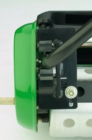 Handlebar height adjusters
The loop-style handlebar itself provides several comfortable grips for a wide variety of operators and grip styles. The lower part of the handlebar closely resembles traditional T-handle walking greens mowers. The loop handlebar is also wrapped, allowing a strong but comfortable grip.
The handlebar system is forward mounted, reducing operator influence on the effective cutting height without sacrificing easy turning. In order to accommodate a wide range of operator heights and operating styles, the handlebar height is adjustable at the rear of the machine. The centers of the adjusters are rubber isolated to minimize vibration of the handlebar, maximizing operator comfort.
Quiet, smooth gas engine
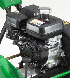 3.2 hp (2.4 kW) gas engine
122 cc 3.2 hp* (2.4 kW) at 3600 rpm engine manufacturer net power tested in accordance with SAE J1349 engine provides plenty of power for even the most demanding mowing conditions.
- Tethered fuel cap, no vent or additional vapor lines
- Taller carbon canister fuel cap
- Additional cooling fins for improved cooling
- Ignition timing changed for reduced emissions to meet California and EPA compliance
- Automotive-style piston rings constructed of steel rather than cast iron
- Automatic compression release (ACR) for smooth, easy starting
- Electronic ignition for reliable consistent starting and operation
- Overhead valves for smooth, quiet, efficient operation
- Tuned to burn efficiently for good fuel economy and to reduced carbon buildup
- Dual-element air cleaner for better performance and extended service
- Fuel tank capacity of 2.7 U.S. qt (2.5 L), with an extended filler neck to reduce spillage and keep contaminants out
* The engine horsepower and torque information are provided by the engine manufacturer to be used for comparison purposes only. Actual operating horsepower and torque will be less. Refer to the engine manufacturer’s Web site for additional information.
Rubber isolators for reduced vibration
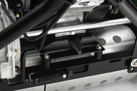 Rear frame
Rubber engine isolators reduce engine vibration, enhancing operator comfort and ensuring a consistent effective height of cut across the width of the machine.
The isolators are mounted to the front and rear frame cross members, which feature a double section for increased strength and durability.
Dual traction rolls for straight tracking and excellent maneuverability
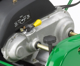 External differential drive
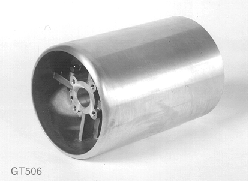 Traction roll
The dual traction rolls for the rear drum are powered by an external differential drive. This design provides equal power to both rolls for the straightest possible tracking. The external differential drive and split drum work together to allow minimal turning efforts and excellent maneuverability when making turns and mowing cleanup passes.
The traction drive rolls are constructed of aluminum, which offers corrosion resistance for durability and long life. The smooth roller surface on the 180SL and 220SL Mowers provide an evenly rolled appearance on greens and other mowing surfaces. The 260SL Mower features a dimpled drum for increased traction in turfs of higher heights, such as tees, collars, aprons, and approaches.
The outside ends of the traction rolls are tapered to provide a smooth transition between the rolled and non-rolled surface areas.
Sealed external differential provides even power distribution for drive rolls and reel
 External differential drive
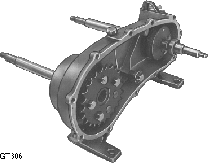 Internal view of differential
The external differential and reel drive sprocket provide even power distribution for a consistent speed to the drive rolls and reel. An internal gear reduction for the reel drive allows a consistent frequency of clip across the entire range of engine throttle.
The drum drive and reel drive sprockets run in a sealed oil bath, resulting in continuous, quiet performance and exceptional component life.
Gear-driven, counter-rotating rotary brush and Greens Tender™ Conditioner for grain and thatch control
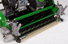 Greens Tender Conditioner
Both the rotary brush and Greens Tender Conditioner (GTC) rotate in the opposite direction of the reel to stand grass up prior to cutting for a consistent quality of cut. This reverse rotation also does an excellent job of standing up the leaf blades just prior to being cut by the reel. A gear-driven design provides the method for counter-rotation. Competitive walking greens mowers utilize belt-drive systems, meaning the groomer rotates in the same direction as the reel.
 Rotary brush
 DT Rotary brush
The rotary brush helps control runners and reduce grain for a truer playing surface by lifting horizontal grass blades so they can be cut by the reel.
The GTC controls runners and reduces grain by lifting horizontal grass blades, but it also slices stolons to promote new growth.
The rotary brush and GTC are powered by an external gear-drive attachment:
The GTC and rotary brush drive feature a quick-engagement lever allowing the operator to either engage or disengage the drive.
High-strength steel reels—Long life, reduced maintenance, and superior toughness
 High-strength steel reels
The 180SL, 220SL, and 260SL Mowers feature a fixed-position reel for even and consistent cutting heights.
- Bedknife-to-reel adjustment knobs provide easy adjustment, infinite range, and pinpoint accuracy for exceptional quality of cut
- High-strength steel reel for long-wear life, reduced maintenance, and resistance to breakage
- Machine frame for each model matches reel width for increased productivity, easy overlapping, and even striping appearance
- A 5-in. (12.7-cm) diameter 11-blade reel for 0.195-in. (5-mm) frequency of clip
- Eccentric adjustment for rear roller allows quick and easy adjustment of paralleling the reel to the rear drum, optimizing height-of-cut consistency
A seven-blade reel is available for the 260SL as a factory-installed option for mowing tees at higher heights of cut.
Special alloys ensure bedknives are tough and resistant
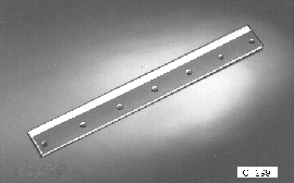 Bedknife
The SL Walk-Behind Greens Mowers feature a large selection of quality bedknives for mowing any area on the golf course, including greens, tees, approaches, collars, aprons, and fairways.
The harder the steel in a bedknife, the longer it maintains an edge. However, a harder steel is also more brittle, making the bedknife more susceptible to damage. A steel that is too soft wears quickly, but is less prone to breaking.
The John Deere bedknife line represents a strength compromise. Special alloys ensure bedknives are tough and resistant to damage over time, without sacrificing the life of the edge.
18-in. (45.72 cm) bedknives for the 180SL
Description |
Bedknife part number |
Minimum height of cut |
| 18-in. tournament |
MT4846 |
0.098 in. (2.5 mm) |
| 18-in. ultra-low-cut tournament |
MT7350 |
0.078 in. (2 mm) |
22-in. (55.88 cm) bedknives for the 220SL
Description |
Bedknife part number |
Minimum height of cut |
| 22-in. bedknife |
ET17533 |
0.126 in. (3.2 mm) |
| 22-in. tournament |
ET17534 |
0.098 in. (2.5 mm) |
| 22-in. long-life fairway |
ET17532 |
0.189 in. (4.8 mm) |
| 22-in. high-cut fairway |
ET17767 |
0.299 in. (7.6 mm) |
| 22-in. ultra-low-cut tournament |
MT7351 |
0.079 in. (2.0 mm) |
| 22-in. tournament with hardened insert |
ET11066 |
0.126 in. (3.2 mm) |
26-in. (66.04 cm) bedknives for the 260SL
Description |
Bedknife part number |
Minimum height of cut |
26-in. bedknife |
MT6947 |
0.126 in. (3.2 mm) |
26-in. long-life fairway |
MT6946 |
0.189 in. (4.8 mm) |
Wide range of roller options, including grooved, smooth, and spiral rollers
There are four roller options available for greens mowing:
There is an additional spiral roller option for tee, approach, and fairway mowing. The other roller options can be considered for non-greens applications as well.
Machined grooved roller with solid end caps
 Grooved roller with solid end caps
Machined grooved roller with continuous grooves
 Grooved roller with continuous grooves
These machined grooved front rollers have continuous grooves throughout the entire width of the roller.
Smooth roller options
 Smooth roller
The smooth rollers are intended for use on greens where the superintendent does not want to cut as aggressively.
-
These rollers are generally used during seasonal or regional conditions where the greens may be wet, soft, or stressed.
-
The hollow front roller is lighter weight and may be the preferred choice in times of extreme stress. It has a similar effect to increasing the benchsetting height of cut due to its reduced weight.
2-in. (50.8-mm) machined spiral-grooved roller
The 2-in. (50.8-mm) diameter spiral-grooved rollers with spiral end caps should be used only when mowing tees, collars, approaches, or fairways. This roller should not be used on greens surfaces.
Easily accessible bedknife-to-reel adjustment
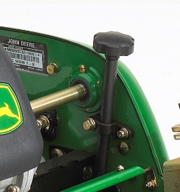 Bedknife-to-reel adjuster tower
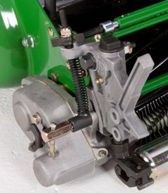 Height-of-cut adjuster tower
Bedknife-to-reel adjustments on the SL Walk Greens Mowers can be made quickly and easily, saving valuable time for technicians to complete other necessary tasks.
The bedknife-to-reel system features two adjuster towers (one for each end of the bedknife) that are easily turned by hand. Simply use a 13-mm wrench or socket to loosen the adjuster tower clamps, turn the towers counterclockwise to increase the bedknife-to-reel gap or clockwise to decrease the gap, and tighten the adjuster tower clamps. The bedknife-to-reel clearance should be adjusted to 0.001 in. (.0254 mm).
All SL Walk Greens Mowers feature a unique adjustment to allow for easy paralleling of the rear drum to the front roller. This can easily be accomplished using a flat plate. The parallel adjustment ensures the rear drum and reel are in the same plane, optimizing a consistent height of cut and cut quality.
Greaseable reel and roller bearings purge unwanted contaminants
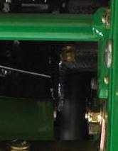 Reel-bearing grease point
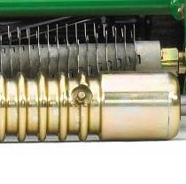 Roller-bearing grease point
Golf courses present some of the toughest conditions for a machine to operate in. The golf course environment presents several challenges, including fertilizers, pesticides, herbicides, and irrigation, to name a few. Each application presents opportunities to damage important reel bearings and roller bearings, drastically shortening the life of these components.
Some competitive machines include sealed bearings as a feature. However, it is important to note that when a machine is washed with cool water after it has been operated, the bearings are naturally hot. When cold water is applied to a hot bearing, the water is sucked into the bearing, immediately introducing contaminants that will shorten the bearing life. With a sealed bearing, there is no way to purge these contaminants out of the bearing.
As a result of the operating conditions, the John Deere SL models offer greaseable reel and roller bearings only, no sealed bearings. After using and cleaning the machine, simply grease the bearings to purge the unwanted contaminants. This greatly increases the life of the reel and roller bearings.
Oil drain channel for clean and easy oil changes
 Standard oil drain channel
The SL Series Walk Greens Mowers lineup features a standard oil drain channel on every machine. The oil drain channel is located at the rear of the engine, just above the rear frame.
The oil drain channel allows quick and clean oil changes.

