 Flotation adjustment
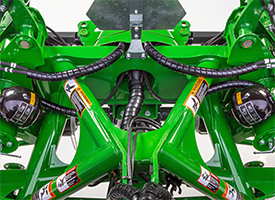 Right-hand and left-hand accumulators
The front and rear mower utilize a hydropneumatic suspension system enabling them to follow ground contours. This simple system requires no springs to adjust the flotation system.
- Double-rod hydraulic cylinders are used to both lift the cutting platform and provide flotation.
- One side of the cylinders is linked to an accumulator to provide flotation.
- The other side of the cylinder is used for lifting the cutting platform for transport or going over headlands.
- Suspension system enables the cutting platform to follow ground contours at productive cutting speeds.
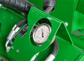
- Flotation is adjusted by opening a valve and using the tractor selective control valve (SCV) lever to alter pressure according to field profile. An easy-to-read gauge enables the operator to confirm that the pressure is within the recommended range. Ground pressure remains consistent even when cutting on uneven ground.
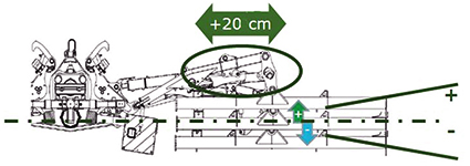
To improve driver comfort, hydraulic overlapping is available with +/- 20 cm (+/- 7.9 in.) if needed, actuated from the monitor in the cab. Ground contour following will be + 24 cm (+ 9.4 in.) upward and – 22.5 cm (- 8.9 in.) downward.
Ground clearance when raising the platform on headlands is approximately 40 cm (16 in.).
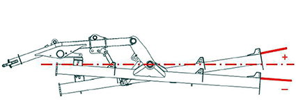
Cylinders work independently to enable the cutting platform to pivot from side to side to give clean cutting even on uneven ground. Angular range:
- + 13.3 degrees / - 8.1 degrees with 50 cm (19.7 in.) overlap.
- + 8.7 degrees / -4.1 degrees with 30 cm (11.8 in.) overlap.
On the R990M Twin Rear-Mounted, a hydraulic breakaway system is standard equipment:
- Should an obstacle be encountered, the cutting platform swings back and lifts up to pass over the obstacle.
- This reduces the potential damage to the cutting unit and decreases maintenance costs.
- For productivity and ease of use, the machine automatically resets on the go.
This flotation system ensures a perfect ground following, reducing soil compaction and providing an excellent cut. Crop stubble is preserved and regrowth is accelerated.
Simple monitor for easy operation of the rear mower's hydraulic functions
The simple monitor enables the operator to easily operate all of the hydraulic functions of the twin rear-mounted mower. The parts of the monitor include the following (arrows in the image above correspond to the alphanumeric values below):
- Polarity inversion display light
- On/off display light
- On/off push button
- Function selector 4:
- A — Front mower suspension adjustment
- B — Rear mower suspension adjustment
- 1 — Working/transport selection
- 2 — Right-hand or left-hand individual mower selection and headland selection
- Push button for transport position
- Three-way selector (left, center, or right)
- Display lights
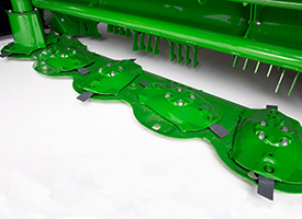 R990M Twin Rear-Mounted Mower
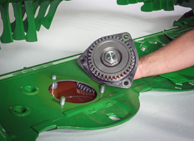 Easily removable pinion gear
Power is transmitted from the 1000 rpm tractor with 44.4-mm (1-3/4-in.) power take-off (PTO) through a central gearcase to the twin rear-mounted cutterbars.
- Each cutterbar is protected by a slip clutch and overrunning clutch
- The cutterbar is securely mounted within the frame for strength and durability
- Power is transmitted to the rotary disks through fully enclosed gears, running in oil, for quiet, smooth, reliable operation
- The high-speed rotary disks cut in the toughest conditions. The disks rotate at 2986 rpm.
- Low-profile design enables cutting close to the ground at a flat angle helping prevent damage to the disks and knives
- Cutting height is adjusted by changing cutting angle
- Pinion gear is easily removed from the top of the cutterbar for service
- Idler gears can be removed from access area after removal of pinion gear
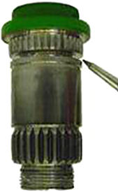 Groove quill on shaft
Groove on quill shaft, designed to shear upon severe impact with a foreign object, reduces the possibility of damage to the internal components of the cutterbar.
Quick-change knives technology
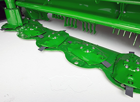 Quick-change knives technology
The cutterbar has been developed to increase productivity through a significant downtime reduction with quick-change knives.
The amount of time spent on changing knives went from 3 minutes per knife to about 15 seconds with quick-change knives. This resulted in saving up to 40 minutes of maintenance time on each platform.
The R990M is fitted with eight disks.
All operators have to do is insert the special tool (attached to the mower) between the disk and spring blade, push it down and remove the knife.
This results in no lost parts during the changing of knives.
Large farms, machinery rings, and contractors need high-quality output and ease of serviceability:
- Each disk is protected against heavy shocks with a shear point located on the disk drive.
- All modules and intermediate gears are quickly and easily interchangeable.
To meet high-quality output, the cutterbar is an oil-immersed gear-driven cutting bed:
- All disks are offering an orbital cutting diameter of 440 mm (17.3 in.)
- With seven disks, the cutting width will be 3.1 m (10.2 ft), and with 8 disks 3.5 m (11.5 ft)
- Disk speeds are 2986 rpm
To meet serviceability, the cutting bed is lubricated for life:
- No oil changes necessary
- Disks are fitted with quick-change knives technology
- Cutting height is from 35 to 85 mm (1.4 to 3.3 in.)
Time needed to change a knife is less than 15 seconds. It is an efficient way to win up to 30 minutes of maintenance time.
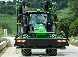 Transport position
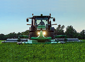 Operating position
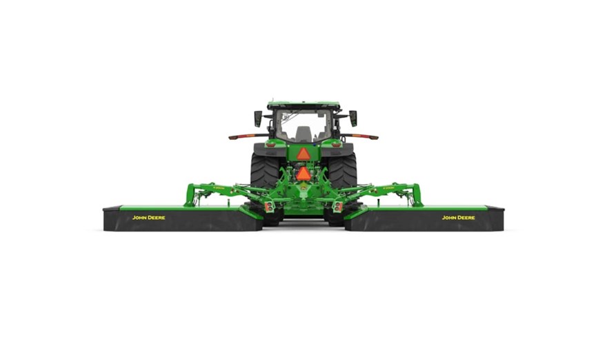
The largest system is the R990M. This TMM system will have three 3.5 m (11.5 ft) mowers for a cutting width of 9.9 m (32.5 ft) per pass.
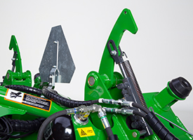 Transport lock for rear mowers (shown on R990M)
To prepare for transporting, the side curtains of the F350M Front-Mounted Mower are manually unlocked and folded into the transport position. This will reduce the overall width during transport. There is no longer a locking lever for the side curtains on the F350M mower. There is an additional locking mechanism for the front mowers to prevent the mower from swinging side to side in transport.
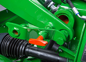 F350M transport lock
Once the front mower is in transport position, return to the cab of the tractor. To fold the rear mowers into the transport position, place dial indicator (4) in picture below on setting 1 and depress button 5 and tractor selective control valve (SCV).
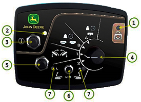 Monitor
The parts of the monitor include the following (arrows in the image above correspond to the alpha-numeric values below):
- Polarity inversion display light
- On/off display light
- On/off push button
- Function selector 4:
- A — Front mower suspension adjustment
- B — Rear mower suspension adjustment
- 1 — Working/transport selection
- 2 — Right-hand or left-hand individual mower selection and headland selection
- Push button for transport position
- Three-way selector (left, center, or right)
- Display lights

