Search Our Inventory: Row Crop Tractor
Search Our Inventory: John Deere 5075E
Search Our Inventory: Skid Steers
Search Our Inventory: John Deere 8370R
Search Our Inventory: Frontier Rotary Cutter
Search Our Inventory: Cotton Picker
Search Our Inventory: Lawn Mower
Search Our Inventory: John Deere Gator
Search Our Inventory: Tillage
Search Our Inventory: Zero-Turn Mower

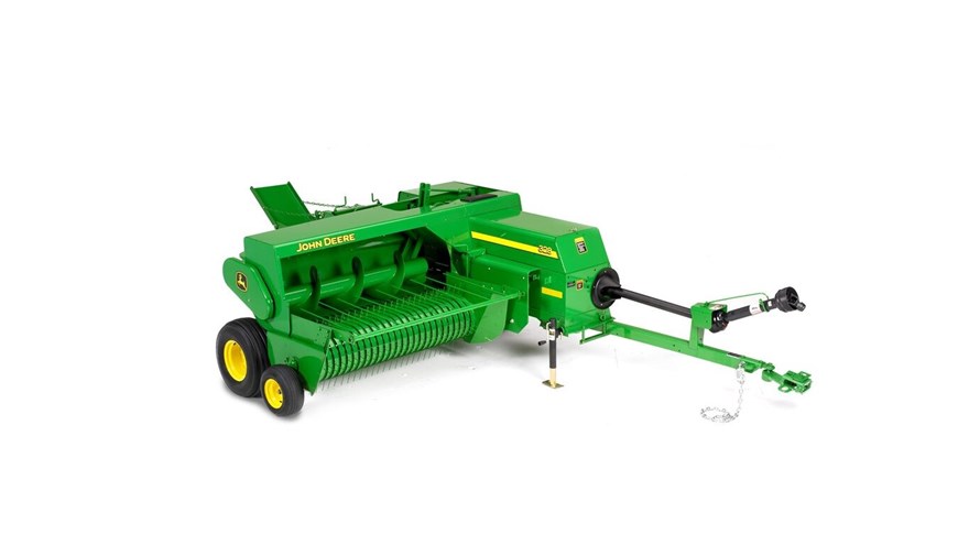
328
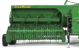
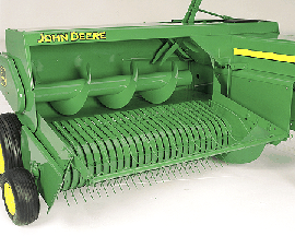
- Full-width feeding pickup
- Adjustable hay compressor
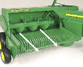
- Deep-flighted auger feeding
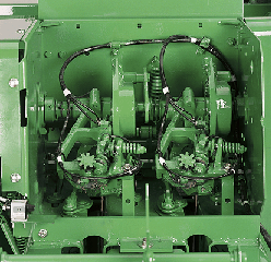
- Accurate knotters
Features
Full-width feeding pickup
Adjustable hay compressor
Deep-flighted auger feeding
Accurate knotters
Hydraulic bale tension available
Uniform bales
Quiet, dependable operation
Key Specs
| Minimum PTO | 26 kW 35 PTO hp |
|---|---|
| Pickup width | 187.9 cm 74 in. |
| Bale size | Height x width 36x46 cm 14x18 cm Length 30.7 to 127 cm 12 to 50 in. |
| Adjustable Hydraulic Bale Density | Optional |
| Plunger - Strokes/minute | 80 spm |
Bale size
| Height x width | 36 x 46 cm 14 x 18 in. |
|---|---|
| Length | 30.5 to 127 cm 12 to 50 in. |
| Maximum volume | |
| Dry bale weight |
Pickup
| Pickup width | 187.9 cm 74 in. |
|---|---|
| Tooth bars/teeth | 4 bars, 104 teeth |
| Lift control | Crank (hydraulic optional) |
| Pickup diameter | 49.5 cm 19.5 in. |
| Compression rack rods |
Auger
| Diameter | 41 cm 16 in. |
|---|---|
| Length | 154.9 cm 61 in. |
| Feed opening |
Plunger
| Strokes/minute | 80 spm |
|---|---|
| Stroke length |
Typing mechanism
| No. of knotters | 2 |
|---|---|
| Twine capacity | 4 |
| Twine type | Plastic or sisal |
| Knot strength (minimum required) | |
| Central lube system | Optional |
| Wire twisters | |
| Wire ball capacity |
Baler dimensions
| Length w/ short tongue | |
|---|---|
| Length w/ long tongue | 576.5 cm 227 in. |
| Width | 274.3 cm 108 in. |
| Height | 170.2 cm 67 in. |
| Weight empty | 1208 kg 2685 lb |
Tractor requirements
| PTO speed | 540 rpm |
|---|---|
| Minimum PTO | 26 kW 35 PTO hp |
Drive mechanism
| Driveline | Equal angle 3 joint category 4 |
|---|---|
| Optional driveline | |
| Pickup | Belt |
| Plunger | Gear and shaft |
| Knotters | Gear and shaft |
| Feeder forks | Gear and shaft |
| Diameter of flywheel |
Drivetrain protection
| PTO | |
|---|---|
| Gearbox | |
| Pickup | Belt slip |
| Needles | Shear bolt/plunger head stop |
| Knotters | Shear bolt |
Tires
| RH Standard tire size | 26x12.0-12, 4 ply |
|---|---|
| RH Optional tire size | |
| LH Standard tire size | 11L-14, 6 ply |
| LH Optional tire size | |
| Gauge Wheels | 1 optional |
| Pickup Gauge Wheels Tires Size | 16.5x6.50-8 |
Lights
| Work | |
|---|---|
| Transport lights |
Density Control System
| Adjustable Bale Density | Mechanical crank |
|---|---|
| Adjustable Hydraulic Bale Density | Optional |
| Bale Counter | Optional |
Bale Ejector
| Available | Optional |
|---|
Bale Chute
| Regular bale chute | |
|---|---|
| Short chute | Optional |
| Long chute | Optional Regular bale chute standard |
| Side bale drop chute | Optional |
| Wagon hitch | Optional |
Additional information
| Date collected |
|---|


